Getting started with EPICS
System components
Broadly speaking, the EPICS toolset enables creation of servers and client applications. Servers provide access to data, reading or writing, locally or over a network. Reading and writing is often done to and from hardware connected to physical components, however data can also be produced or used elsewhere. Physical I/O, however is the central task of any control system, including EPICS.
Clients can display, store and manipulate the data. Client software ranges from (graphical and command line) user interface tools to powerful services for data management.
The basic components of an EPICS-based control system are:
IOC, the Input/Output Controller. This is the I/O server component of EPICS. Almost any computing platform that can support EPICS basic components like databases and network communication can be used as an IOC. One example is a regular desktop computer, other examples are systems based on real-time operating systems like vxWorks or RTEMS and running on dedicated modular computing platforms like MicroTCA, VME or CompactPCI. EPICS IOC can also run on low-cost hardware like RaspberryPi or similar.
CWS, or Client WorkStation. This is a computer that can run various EPICS tools and client applications; typical examples are user interface tools and data archiving. CWS can be desktop computer, a server machine or similar, and is usually running a “regular” (as opposed to real-time) operating system like Linux, Windows or MacOS.
LAN Local Area Network. This is just a standard Ethernet-based (or wireless) communication network that allows the IOCs and CWS’s to communicate.
A simple EPICS control system can be composed of one or more IOCs and Client WorkStations that communicate over a LAN (Figure 1). Separation of clients and servers makes configuration of the systems easier and also makes the system more robust. Clients and servers can be added to and removed from the system without having to stop the operation.
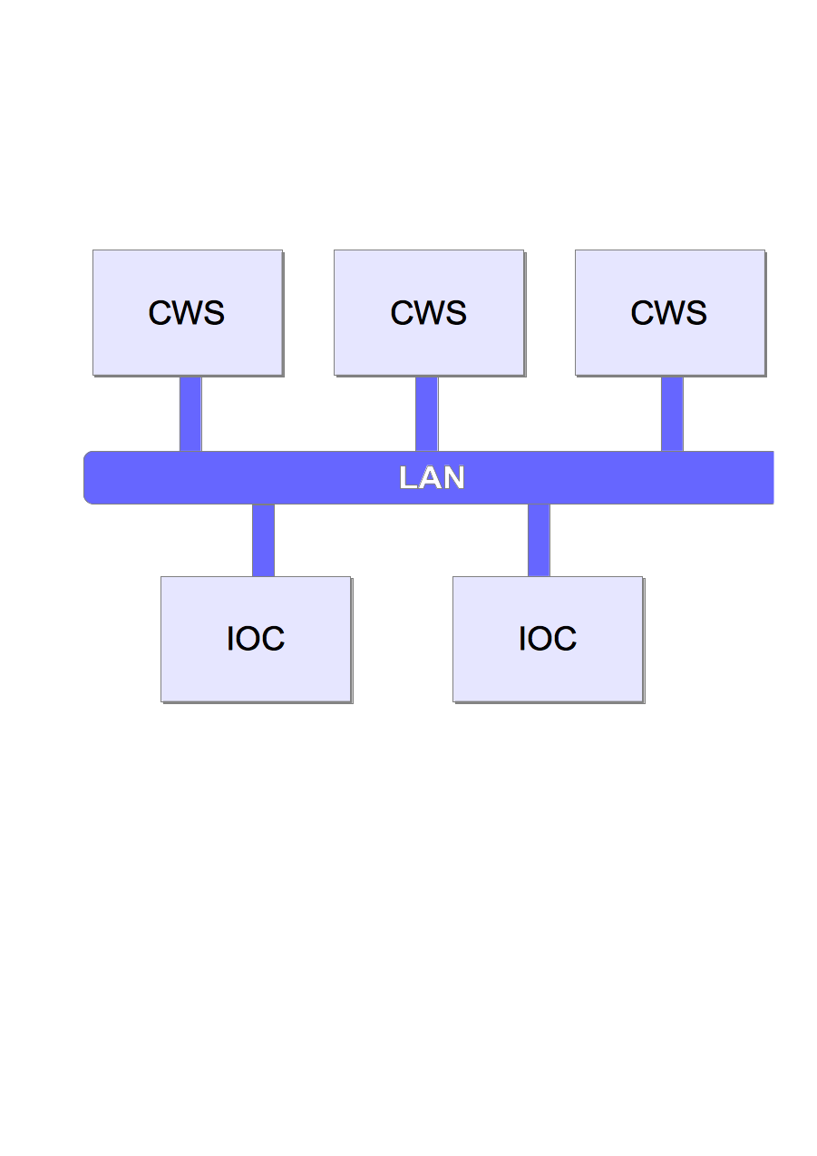
Figure 1. A simple EPICS control system structure.
In addition to these basic components of a “classical” EPICS control system, it is also possible to implement servers (aka services) for data that are not “process I/O” (real-time values from a controlled process) or attached to hardware. These other services can for example provide configuration or calibration data, or computing services like particle beam modeling. Since all the services “speak” the same protocol and exchange the same type of data structures, the data source is transparent to the client software (i.e., you do not need to know in advance where the data comes from or how it is obtained.) In this sense, the IOC can be regarded as a special type of server that handles process data and connects to real field hardware (in many cases, but not necessarily.)
The EPICS software components Channel Access (CA) and pvAccess (PVA) provide the protocols and structures that enable network transparent communication between client software running on a CWS and an arbitrary number of IOCs and other servers. More details about CA and PVA are provided in later chapters.
Basic Attributes
The basic attributes of EPICS are:
Tool Based: EPICS provides a set of interacting tools and components for creating a control system. This minimizes the need for customer-specific coding and helps ensure uniform operator interfaces.
Distributed: An arbitrary number of IOCs and CWSs can be supported. As long as the network is not saturated, there is not a single bottleneck. If a single IOC becomes saturated, its functions can be spread over several IOCs. Rather than running all applications on a single CWS host, the applications can be spread over many CWSs.
Event Driven: The EPICS software components are all designed to be event driven to the maximum extent possible. For example, an EPICS client may, instead of having to query IOCs for changes, request to be notified of a change. This design leads to efficient use of resources, as well as quick response times.
High Performance: An IOC can process tens of thousands of data items (“database records”, see below) per second. Clients and servers can handle systems with millions of process variables, with minimized network overhead.
Scalable: As a distributed system, EPICS can scale from systems with a single IOC and a few clients to large installations with hundreds of IOCs and millions of I/O channels and process variables.
Robust: failure of a single components does not bring the whole system down. Components (IOCs, clients) can be added to and removed from the system without having to stop operation of the control system. The components can withstand intermittent failures of the interconnecting network and recover automatically when the network recovers from failure.
Process-variable based: In contrast to some other control system packages, EPICS does not model control system (I/O) devices as objects (as in object-oriented programming) but rather as data entities that describe a single aspect of the process or device under control, thus the name “process variable”, or “PV”. A typical PV can represent any one of various attributes such as temperature or (electric) current. This design is typical in process control systems. The pros and cons of this design are shortly discussed in the Appendix.
IOC Software Components
An EPICS IOC at its core is a software entity or a process that contains the following software components:
IOC Database: A memory resident database containing a set of named records of various types. The records host the process variables that were mentioned above.
Scanners: The mechanisms for processing records in the IOC database.
Record Support: Each record type has an associated set of record support routines to implement the functionality of the record type.
Device Support: Device support routines bind I/O data to the database records.
Device Drivers: Device drivers handle access to external devices.
Channel Access or pvAccess: The interface between the external world and the IOC. It provides the interface for accessing the (EPICS) database via the network.
Sequencer: A finite state machine. Strictly speaking, this is an external module and not included in the EPICS core software distribution.
Let us briefly describe the major components of the IOC and how they interact.
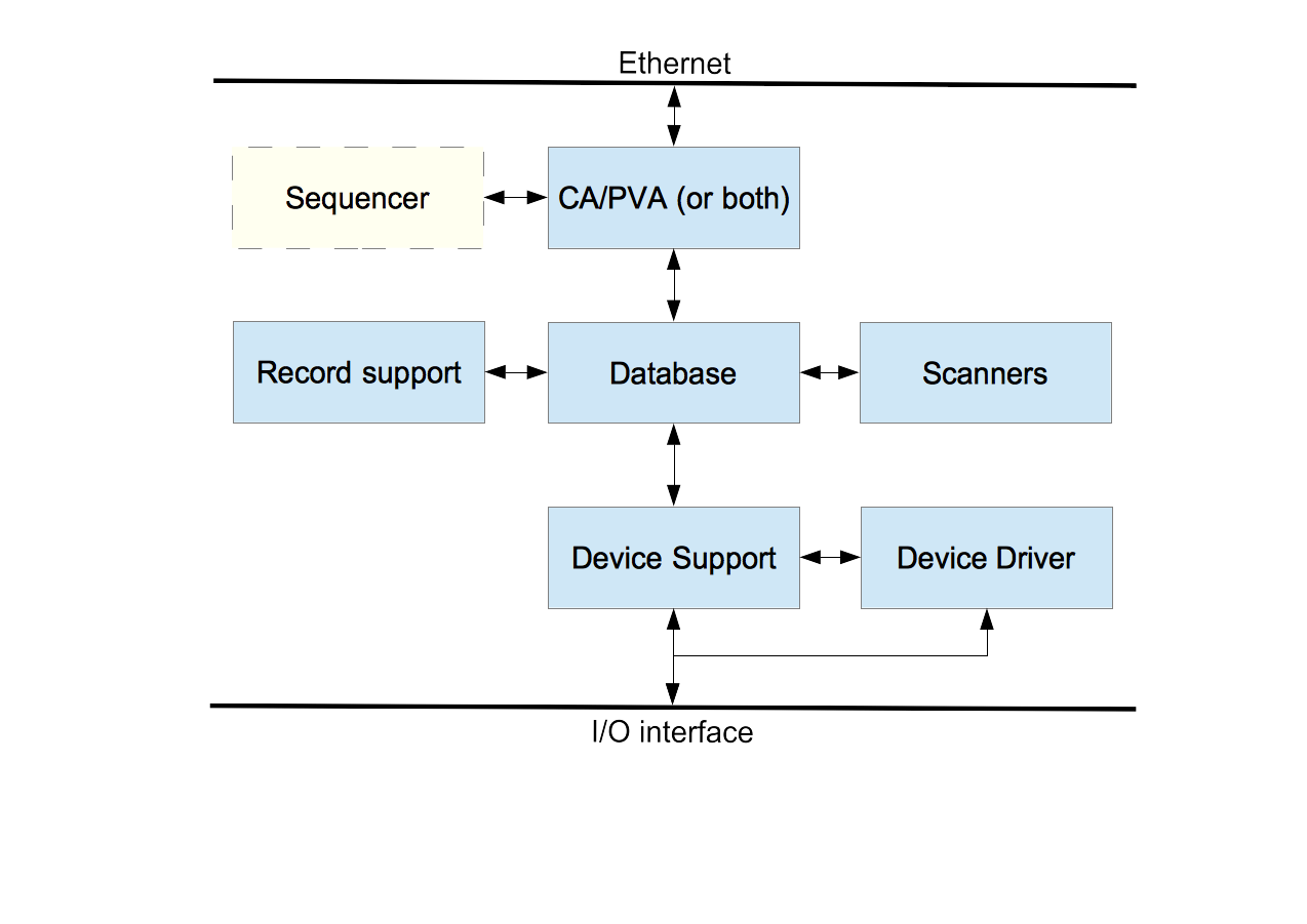
Figure 2. EPICS IOC components.
IOC Database
The heart of each IOC is a process database. This database is memory resident (i.e., not stored on a hard disk or other permanent memory device) and has nothing to do with the more commonly known relational (aka SQL) databases.
The database defines the functionality of the IOC: what process data it provides, how is the data handled and stored. The database can contain any number of records, each of which belongs to a specific record type. The record type defines the type of data that the record handles and a set of functions that define how the data are handled. Record type-specific metadata, also known as “properties” is included in the records to configure and support the operation. For instance, an analog input (ai) record type supports reading in values from hardware devices and converting them into desired (engineering) units. It also provides limits for expected operating ranges and alarms when these limits are exceeded. EPICS supports a large and extensible set of record types, e.g. ai (Analog Input), ao (Analog Output), etc.
The metadata, known as “fields” is used to configure the record’s behavior. There are a number of fields that are common to all record types while some fields are specific to particular record types. Every record has a record name and every field has a field name. The record name must be unique across all IOCs that are attached to the same TCP/IP subnet, to enable the client software to discover any record on the subnet and to access its value and other fields.
record(ai, "Cavity1:T") #type = ai, name = “Cavity1:T”
{
  field(DESC, “Cavity Temperature”) #description
  field(SCAN, “1 second”) #record update rate
  field(DTYP, “XYZ ADC”) #Device type
  field(INP, “#C1 S4”) #input channel
  field(PREC, “1”) #display precision
  field(LINR, “typeJdegC”) #conversion spec
  field(EGU, “degrees C”) #engineering units
  field(HOPR, “100”) #highest value on GUI
  field(LOPR, “0”) #lowest value on GUI
  field(HIGH, “65”) #High alarm limit
  field(HSV, “MINOR”) #Severity of “high” alarm
}
Figure 3. Example of an EPICS database record. Only a subset of fields is defined here.
Database records can be linked with each other. For example, records can retrieve input from other records, trigger other records to process, enable or disable records and so on.
By linking a combination of records together, the EPICS database becomes a programming tool. Using this, even very sophisticated functions can be achieved with the database. In addition, as this logic resides on the IOC, it is not dependent on any client software to work. By taking advantage of this, many client programs can be “thin” and just display or write the values in the database records. Figure 4 below illustrates a simple example of record linking: if the average temperature of the two sensors T1 and T2 is over 10 degrees, the chiller is switched on. This database contains four records: two analog inputs (ai), one binary output (bo) and one calculation (calc).
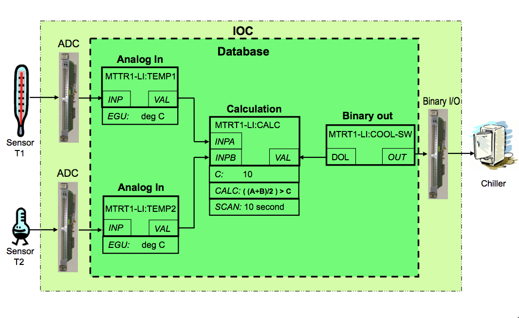
Figure 4. Example of record linking. From [2].
Data structures are provided so that the database can be accessed efficiently. Most software components do not need to be aware of these structures because they access the database via library routines.
Database Scanning
Database scanning is the mechanism to process a record. Processing means making the record perform its task, for instance reading an I/O channel, converting the read value to engineering units, attaching a timestamp to the value or checking the alarm limits. How data are handled when a record is processed depends on the record type.
Four basic types of record scanning are provided: Periodic, Event, I/O Event and Passive. All these methods can be mixed in an IOC.
Periodic: A record is processed periodically. A number of time intervals are supported, typically ranging from 10 Hz to 0.01 Hz. Ranges are configurable to support higher and lower rates.
Event: Event scanning happens when any IOC software component posts an (EPICS software) event, such as a new temperature sensor measurement value.
I/O Event: The I/O event scanning system processes records based on external events like processor interrupts. An IOC device driver interrupt routine must be available to accept the external interrupts. An I/O Event does not necessarily have to be an interrupt in the traditional sense of a CPU interrupt, though.
Passive: Passive records are not scanned regularly or on events. However, they can be processed as a result when other records that are linked to them are processed, or as a result of external changes such as new values set over network using Channel Access.
Record Support, Device Support and Device Drivers
Access to the database does not require record type-specific knowledge; each record type provides a set of record support routines that implement all record-specific behavior. Therefore, IOCs can support an arbitrary number of records and record types. Similarly, record support contains no device specific knowledge, giving each record type the ability to have any number of independent device support modules. If the method of accessing the piece of hardware is more complicated than can be handled by device support, then a device driver can be developed. Sometimes splitting functionality between device support (when it is record type-specific) and a driver (when the code handles device-specific details) is a good practice.
Record types that are not associated with hardware do not need to have device support or device drivers. One example is a calculation (“calc”) record that reads its input from other records, performs a calculation and then (optionally) forwards the result to other records.
The IOC software design allows a particular installation and even a particular IOC within an installation to choose a unique set of record types, device types, and drivers. The remainder of the IOC system software is unaffected.
To give an overview of how the separation works, let us look at the tasks of the record support. Every record support module must provide a record processing routine to be called by the database scanners. Record processing consists of some combination of the following functions (all record types do not need all functions):
Input: Read inputs. Inputs can be obtained, via device support routines, from hardware, from other database records via database links, or from other IOCs via Channel Access (CA) or pvAccess (PVA) links.
Conversion: Conversion of raw input to engineering units or engineering units to raw output values.
Output: Write outputs. Output can be directed, via device support routines, to hardware, to other database records within the same IOC via database links, or to other IOCs via CA or PVA links.
Raise Alarms: Check for and raise alarms.
Monitor: Trigger monitors related to CA or PVA callbacks.
Link: Trigger processing of linked records.
The same concept is applied to the device support and device driver modules: each support module has to define a set of functions so that it can become a part of the IOC software.
Database Monitors
The mechanism to send notifications when a database value changes is called “database monitors”. The monitor facility allows a client program to be notified when database values change without having to constantly poll the database. These can be configured to specify value changes, alarm changes, and/or archival changes.
Database monitors are supported by the EPICS standard protocols Channel Access and pvAccess.
Network protocols
EPICS provides network transparent access to IOC databases by supporting the following network protocols for data exchange.
Channel Access
Channel Access is based on a client/ server model. Each IOC provides a Channel Access server that is able to establish communication with an arbitrary number of clients. Channel Access client services are available on both CWSs and IOCs. A client can communicate with an arbitrary number of servers.
Client Services
The basic Channel Access client services are:
Search: Locate the IOCs containing selected process variables and establish communication with each one.
Get: Get value plus additional optional information for a selected set of process variables.
Put: Change the values of selected process variables.
Monitor: Request to have the server send information only when the associated process variable changes state. Any combination of the following state changes can be requested: change of value, change of alarm status and/or severity, and change of archival value. Many record types provide hysteresis factors for value changes.
In addition to process variable values, any combination of the following additional information (“metadata”) may be requested:
Status: Alarm status and severity.
Units: Engineering units for this process variable.
Precision: Precision with which to display floating-point numbers.
Timestamp: Time when the record was last processed.
Enumeration: A set of ASCII strings defining the meaning of enumerated values.
Graphics: High and low limits for configuring widgets and graphs on a graphical user interface (GUI).
Control: High and low control limits; operational limits for the record.
Alarm: The alarm status (HIHI, HIGH, LOW, and LOLO) and severity for the process variable.
Search Server
Channel Access provides an IOC resident server, which waits for Channel Access search messages. These are UDP broadcasts that are generated by a Channel Access client (for example when an Operator Interface task starts) when it searches for the IOCs containing process variables it uses. This server accepts all search messages, checks to see if any of the process variables are located in this IOC, and, if any are found, replies to the sender with an “I have it” message.
Connection Request Server
Once the process variables have been located, the Channel Access client issues connection requests for each IOC containing process variables the client uses. The connection request server, in the IOC, accepts the request and establishes a connection to the client. Each connection is managed by two separate tasks: ca_get and ca_put. The ca_add_event requests result in database monitors being established. Database access and/or record support routines provide the value updates (monitors) via a call to db_post_event.
Connection Management
Each IOC provides a connection management service. If a Channel Access server fails (e.g. its IOC crashes) the client is notified and when a client fails (e.g. its task crashes) the server is notified. If a client fails, the server breaks the connection. If a server crashes, the client automatically re-establishes communication when the server restarts.
pvAccess
pvAccess is a modern replacement and an alternative to Channel Access available in EPICS 7. PvAccess adds a number of capabilities to EPICS that augment the set of services provided by Channel Access. With pvAccess, structured data can be transported with a high efficiency and is capable of handling big data sets; this has been achieved with a number of optimizations:
Data structure introspection and data transport have been separated so that structure information needs to be carried only once per connection.
Monitors send only the items of a data structure that have changed.
Several under-the-hood optimizations in data manipulation have been made (reduce copying, etc.) In application testing pvAccess has been able to utilize 96-99% percent of the available theoretical bandwidth of a 10 Gbit Ethernet link which is close to the limit of what is achievable in practice.
Client Services
The basic pvAccess client services are similar to Channel Access, with a couple of additions:
Search: Locate the IOCs that contain the process variables of interest and establish communication with each one.
Get: Get value plus additional optional information for a selected set of process variables.
Put: Change the values of selected process variables.
Add Monitor: Add a change of state callback, similar to Channel Access.
PutGet: Change the value of a PV, process the EPICS record and read back the value in one atomic operation.
ChannelRPC: A “Remote Procedure Call” [3] communication pattern. This is similar to PutGet, but the communication is asymmetric, i.e., the data sent by client (“request”) is different from the data structure that the server sends back. This pattern can be described as a query with parameters. Examples could be to ask a calibration service for parameters for a certain device, or a beam physics server for calculated beam parameters at certain coordinates of the accelerator.
For the IOC, an IOC resident server (qsrv) provides the interface to access the process database records. Basic access to a single PV provides the equivalent function to channel access. In addition, qsrv provides the possibilities to create data structures that combine data from different database records into structures that are transported as units. Since EPICS 3.16, the IOC core is able to guarantee atomic access to the records, meaning that the data in the structure that qsrv provides is guaranteed to be a result of a single processing (or better expressed, that the records do not change their values while qsrv is assembling the data structure.) This applies also to puts, meaning that all values are written to the addressed records before the records are processed. This way, coherence of parameters for an operation can be guaranteed.
Search Server
Like in Channel Access, qsrv waits for search messages. The server accepts all (UDP) search messages, checks to see if any of the process variables are located in this IOC, and if any are found, replies to the sender with an “I have it” message.
Connection Request Server
In pvAccess, the process of how a client and a server establish the communication channel is slightly different from Channel Access and contains two stages. The first stage is exchanging introspection data. In this stage, the server communicates to the client the structure of the data to be exchanged. Both sides can then create the necessary placeholder structures for the communication. In the second stage the actual data can be exchanged, using the allocated data structures.
Connection Management
pvAccess provides a connection management service similar to Channel Access.
EPICS database and network transport
It should be noted that the access methods (pvAccess, Channel Access) do not provide access to the EPICS database as records. This is a deliberate design decision. This allows changes to be made in the database structures or new record types to be added without impacting any software that accesses the database via PVA or CA, and it allows these clients to communicate with multiple IOCs having differing sets of record types.
Client Workstation Tools
EPICS offers a range of tools and services that are executed on the client workstations. These can be divided into two groups based on whether or not they use Channel Access and/or pvAccess. CA/PVA tools are real time tools, i.e. they are used to monitor and control IOCs. These tools are not included in the EPICS “base” distribution and have to be downloaded separately. The tools are implemented in different languages and technologies and the users should select which tools are the best suited to their particular setup and infrastructure.
Examples of CA/pvAccess Tools
A large number of CA/PVA tools have been developed. The following are some representative examples.
CS-Studio: Control System Studio, an application bundle with many available plug-ins like display managers (BOY, Display Builder), data visualization/charting tools (DataBrowser), and so on.
EDM: Extensible Display Manager. One of the several alternative display managers. Other popular alternatives are caQtDM (based on the Qt framework), medm (Motif Extended Display Manager, a legacy tool), just to name a couple.
Alarm Handler. General-purpose alarm handler driven by an alarm configuration file.
Sequencer: Runs in an IOC to implement state machines.
Archiver Appliance: Collects data from EPICS servers (CA,PVA) and stores the data in time-series files so that they can be later retrieved and analyzed for correlating events and monitoring the performance of the “machine”, i.e., the device or facility under control.
Channel Finder (Indexing Service): A tool to manage (list, tag, categorize) the EPICS records in a system. This is a powerful tool to manage and provide hierarchy and different viewpoints to the potentially very large number of records. With this service, abstract views to the flat namespace of the records can be provided. For example, listing all vacuum pumps in the system, or horizontal position of the beam in the accelerator as measured by the Beam Position Monitors.
Examples of other Tools
VDCT: A Java based database configuration tool, which can be used to design and configure EPICS databases, and is able to visualize the records and their connections.
SNC: State Notation Compiler. It generates a C program that represents the states for the IOC Sequencer tool.
References and further reading
Control Theory (https://en.wikipedia.org/wiki/Control_theory)
http://epics.web.psi.ch/training/handouts/e_EPICS_Training_at_PSI.ppt
EPICS Application Developer’s Manual (version dependent, see for instance http://www.aps.anl.gov/epics/base/R3-15/5-docs/AppDevGuide/AppDevGuide.html)
Recent Advancements and Deployments of EPICS Version 4, Greg White et. al., ICALEPCS 2015, Melbourne, Australia.
Appendix: Objects vs Process Variables discussion
As discussed in Chapter 2, EPICS is based on a “flat”, i.e., non-hierarchical set of records, which represent the Process Variables [1] of the control system. This has a number of pros and cons:
Pros:
Easy to adjust to any specific case without need of detailed modeling of the devices.
Efficient communication: only the data of interest needs to be transported.
PVs are modular building blocks that can be mixed and matched as needed.
Even complex functionality can be implemented without (traditional) programming.
Cons:
Lack of abstraction; control of complex entities has to be implemented on top of the PVs.
Management of discrete data items is hard; lack of atomic actions [4].
Advantages of object-oriented programming (code reuse, encapsulation, etc.) cannot be utilized.
One can extend these lists and argue about them but the above are the most common.
There is no single truth saying that this model is better or worse than other conceivable models. It depends on the use case and how much weight is put on each different factor.
However, the new features in EPICS 7 have been added to mitigate the lack of abstraction and atomic actions. The structured data model in EPICS 7 allows construction of complex structures to represent abstract entities. Further, these entities can be built from the existing building blocks, thus the flexibility is retained; in a way this is even better than strict modeling because the abstraction can be added on top of the working system afterwards. Also, atomic actions – to the extent they can be implemented in a distributed system – have been added, thus removing the need of complicated workaround solutions.